Motor Control Circuit Diagram
Circuit motor control diagram dc electrical electronics engineering 3 wire motor control circuit Motor control circuit wiring
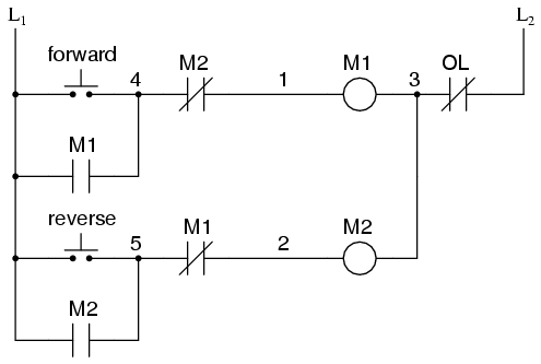
Electrical and Electronics Engineering: Dc motor control circuit diagram
Schematics jog Latching instrumentation Motor control circuit forward wiring reverse power circuits instrumentationtools reversing instrumentation
Motor control switch circuits logic auxiliary timer program contacts ladder diagram plc forward contact open pushbutton normally programming circuit reverse
Motor circuits and control – applied industrial electricityWiring diagram of motor control center Electrical and electronics engineering: dc motor control circuit diagram.
.


